
This project is in BETA status. It features:
The reference design / prototype unit was designed for 100 watts, however this design can undoubtedly be scaled for lower or higher power capability.
If you are interested in this project, please join the Radio Artisan discussion group.
As mentioned above, this project is in beta status. That means it is not a finished, polished product. The documentation may be is incomplete. Do not attempt this project unless you really want to experiment and you have some experience with Arduino programming and building advanced amateur radio projects. If you want a ready-made kit, please look elsewhere,for now
.
Note that lethal voltages can be present on various points in an antenna tuner, even at lower RF power levels. If you are not experienced with high voltage, do not risk your health or life. Safety first.
Here's a nice implementation of this tuner by Glenn, VK3PE, with fabricated PC boards and a customized display.
I have built one unit which was intended to be a prototype. It worked so well that I haven't built another one and the prototype continues to be used in my shack on a nearly daily basis. The bottom line is, it works rather well. I would eventually like to build a QRP model with latching relays and sleep mode.
If you would like to improve this code or hardware design and/or fork the project, please do.
The Arduino controls a relay-switched matching network consisting of capacitors and inductors. The reference hardware design is a balanced L, with the capacitor bank switched between the input and output of the network to provide Hi Z and Lo Z impedance transformation. Standing Wave Ratio or SWR is sensed by the Arduino by feeding a forward RF detected voltage and a reverse RF detected voltage from an SWR bridge into two Arduino analog pins. When the Arduino senses an SWR over a configurable threshold, the unit begins a tune sequence in which numerous relay combinations are tried to find the best match within a configurable amount of time. When an acceptable match is found, the tuning routine stops.
The Arduino also frequency-counts the RF signal and stores tuning combinations along with the frequencies in non-volatile EEPROM memory for future use. Before invoking a tuning combination search, the list of past tuning combinations is queried to see if a close frequency match is available.
Optionally, the unit interfaces to a transceiver to periodically query its frequency which is used to automatically switch the tuning network when the band is changed or if the frequency changes more than a configurable threshold. The code can be configured for rig pass-through where the Arduino will pass through an rig commands from the computer to the rig, and vice versa. This makes the Arduino look transparent to the computer, but still allows the Arduino to query frequency information from the rig.
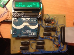
An optional LCD display shows SWR, the currently tuned frequency, the radio frequency, and current tuning network values.
[youtube=http://www.youtube.com/watch?v=SoVW1cxrKOE]
The reference hardware design ad prototype I built is using an Arduino Uno and has 100 watt capability.
Note that while an Arduino Uno is specified, other Arduino variants or "bare" Atmel AVR chips such as the ATmega328 or ATmega2560 can be used to save costs, conserve power, or create a more compact unit, especially if certain features are not needed, such as the computer USB interface.
Schematics can be found on Github.
General Technical Description
RF power from the transmitter comes into the port currently label rf in. A tandem match direction coupler produces forward and reverse voltages which are proportional to forward and reflected power. Both of these voltages are fed to dual unity gain op amps to provide buffering. The buffered voltage is fed to analog pins on the Arduino to sense calculate standing wave ratio (SWR).
The RF signal is sampled after the tandem match directional coupler. This voltage is fed to a limiter which converts the high voltage sine wave to a 0 to +5V square wave which is then frequency divided by 4 using a dual D-type flip flop. The divided signal is routed to the Arduino which counts the signal in order to detect the transmitter frequency.
The RF signal then travels through a 1:1 balun which converts the unbalanced transmitter output to a balanced signal. The tuning network is a balanced L design. Inductors and capacitors are switched in and out of the circuit by relays. Additionally, the entire capacitor bank is switch by relays unto the output and input of the tuning network in order to provide impedance step up ("HiZ") and impedance step down ("LoZ") capability. Relays are controlled by the Arduino via its I2C bus which interfaces with two I2C expander ICs. These each provide eight output lines which feed darlington transistor buffer ICs, which in turn activate the relays. A switch is provided to interrupt the voltage to one side of the network, deactivating one leg of inductors, in order to provide an option to feed an unbalanced load.
An LCD unit interfaces with the Arduino using the I2C bus. (A classic four bit interface unit can be used as well, if desired.) A bank of LEDs provide indication of relay operation and make a nice blinky light show when tuning. A momentary switch can be depressed to manually invoke tuning and a lock switch, when closed, inhibits automatic triggering of tuning. Two expansion ports provide access to all major pins for future add ons, like antenna and transmitter switching units or external SWR sensors.
Pins for core administrative functions are defined here:
#define pin_led 13
#define pin_tune_in_progress 0 // indicator - goes high when tuning (0 = disable)
#define pin_tuned 0 // indicator - goes high when tuned (0 = disable)
#define pin_untunable 0 // indicator - goes high when untunable (0 = disable)
#define pin_frequency_counter 5 // input - frequency counter (dummy entry - hard coded in frequency counter library)
#define pin_tune_lock 0 // input - ground to lock tuning (0 = disable)
#define pin_forward_v A0 // input (analog) - SWR sensor forward voltage
#define pin_reflected_v A1 // input (analog) - SWR sensor reverse voltage
#define pin_voltage_control 7 // output - controls SWR sensor voltage attenuator
#define pin_wakeup 2 // input - use with FEATURE_SLEEP_MODE - low wakes unit up
#define pin_awake 0 // output - use with FEATURE_SLEEP_MODE - goes high when unit is awake (0 = disable)
#define pin_manual_tune 0 // input - ground to initiate tuning (0 = disable)
#define rig_1_control_tx A2 // rig serial port - rig RX line / Arduino TX line
#define rig_1_control_rx A3 // rig serial port - rig TX line / Arduino RX line
These pins are basically used for everything except driving relays for inductor and capacitor switching, antenna switching, transmitter switching, and Hi Z/Lo Z switching. The pin definitions are most self-explanatory and pins can be substituted as long as the pin has the appropriate capabilities (i.e. analog). Note the rig TX and RX lines are for a SoftwareSerial RS-232 port.
Features are turned on and off at compile time here:
#define FEATURE_DISPLAY
#define FEATURE_LCD_I2C
#define FEATURE_SERIAL
#define FEATURE_SERIAL_HELP
#define FEATURE_COMMAND_LINE_INTERFACE
#define FEATURE_FREQ_COUNTER
//#define FEATURE_RECEIVE_BYPASS
//#define FEATURE_SLEEP_MODE
//#define FEATURE_RIG_INTERFACE
//#define FEATURE_RECEIVE_FREQ_AUTOSWITCH
//#define FEATURE_RIG_CONTROL_PASS_THROUGH
//#define FEATURE_LCD_I2C_STATUS_COLOR
These activate various serial port messages for events. The most useful one for code troubleshooting is DEBUG_STATUS_DUMP which can be used with the CLI S and P commands to get an instant status of the tuner.
#define DEBUG_I2C_PIN_WRITE
#define DEBUG_EEPROM
#define DEBUG_RELAY_TEST
#define DEBUG_COMMAND_BUFFER
#define DEBUG_MEASURE_SWR
#define DEBUG_STATUS_DUMP
#define DEBUG_STATUS_DUMP_SWR_CACHE
#define DEBUG_CHECK_STATE
#define DEBUG_SERVICE_TUNING
#define DEBUG_SERVICE_TUNING_VERBOSE_FREQ
#define DEBUG_RIG
#define DEBUG_RECEIVE_FREQ_AUTOSWITCH
#define DEBUG_TUNE_BUFFER
#define DEBUG_REAL_DEEP_STUFF
#define DEBUG_DONT_TUNE
#define DEBUG_NO_FREQ
#define DEBUG_SERIAL
FEATURE_DISPLAY
This enables the LCD display code. The LiquidCrystal library is used and typical 4 bit LCD displays can be used with the appropriate pins defined in this line:
LiquidCrystal lcd(12, 11, 10, 9, 8, 7);
FEATURE_LCD_I2C
Enables support for the Adafruit I2C RGB display. Comment out the LiquidCrystal declaration when using an I2C display. Note that the I2C interface pins are not configured in the code, these are "hardcoded" into whatever Arduino you are using.
FEATURE_SERIAL
Enables base serial port functionality.
FEATURE_SERIAL_HELP
Activates a basic command line help menu that is accessed using a ? (question mark). The help menu items that are displayed depends on what functionality is enabled.
Sample menu:
CLI Help
B Tune Buffer
C Clear Tune Buffer
D Debug
L Tune Lock
M Manual Tune
P Periodic Status
S Status
U Tune Unlock
FEATURE_COMMAND_LINE_INTERFACE
Enables the command line interface or CLI. Some commands are dependent on what features are enabled. See Command Line Interface below for details on CLI commands.
FEATURE_FREQ_COUNTER
This feature declaration is going to be deprecated. The frequency counter will be a standard required piece of hardware.
FEATURE_RECEIVE_BYPASS
If enabled the tuner will bypass the matching network when no transmit signal is detected. The delay time is set with:
#define RECEIVE_BYPASS_DELAY 200
FEATURE_SLEEP_MODE
Enables automatic sleep mode. The unit will put the AVR in power saving sleep mode after a certain amount of inactivity time. The inactivity time is defined here (units are mS):
#define GO_TO_SLEEP_TIMER 5000
A pin can be configured to go high when the unit is awake:
#define pin_awake 0
This pin could be used to drive a relay or transistor that activates and deactivates ancillary circuits in order to conserve power.
The unit can be awoken from sleep mode by driving the following pin high:
#define pin_wakeup 2
FEATURE_RIG_INTERFACE
This feature activates rig interface functionality. The rig interface retrieves frequency information from the rig in order to perform autoswitching in receive mode. It also supports commands to the rig via the Command Line Interface to invoke tuning. Read the Rig Interface section below for details.
FEATURE_RECEIVE_FREQ_AUTOSWITCH
Thus feature reads the rig frequency regularly and will switch the tuner to the closest stored match when the rig receive frequency / band is changed.
FEATURE_RIG_CONTROL_PASS_THROUGH
This feature passes commands from the computer coming into the USB port and forwards them out the rig serial port, and also sends responses from the rig back to the computer, effectively making the Arduino look transparent to the computer. This allows computer logging programs to continue to control the rig and also allows the Arduino to query the radio. This feature seem to work best when serial port and rig port are set to the same baud rate. (Probably some optimization is needed for this code.) Note that you cannot currently use this feature and FEATURE_COMMAND_LINE_INTERFACE simultaneously, however a future update will allow multi-native serial port units like the Arduino Mega to support both a computer rig pass through port and a serial command line port.
FEATURE_LCD_I2C_STATUS_COLOR
This feature makes an RGB I2C LCD display change colors based on the tuner state. Colors for the various states are configured here:
#define LCD_I2C_STATUS_COLOR_TUNED 0x2
#define LCD_I2C_STATUS_COLOR_UNTUNED 0x1
#define LCD_I2C_STATUS_COLOR_TUNING 0x4
The "lookups" for the colors are here:
#define RED 0x1
#define YELLOW 0x3
#define GREEN 0x2
#define TEAL 0x6
#define BLUE 0x4
#define VIOLET 0x5
#define WHITE 0x7
T1: 2 windings: 18 turns #20 AWG enameled on T130-2 core, each wire 28" (71 cm)
T2, T3: primary: pass RG-58 through core; secondary: 40 turns #30 AWG enamled on T50-2 core (see construction notes for directional coupler)
L1, L9: 0.08 uH, 4 turns #20 AWG enameled on T80-2 core (design change pending)
L2, L10: 0.16 uH, 5 turns #20 AWG enameled on T80-2 core (design change pending)
L3, L11: 0.32 uH, 8 turns #20 AWG enameled on T80-2 core
L4, L12: 0.64 uH, 11 turns #20 AWG enameled on T80-2 core
L5, L13: 1.3 uH, 12 turns #20 AWG enameled on T94-2 core
L6, L14: 2.6 uH, 17 turns #20 AWG enameled on T94-2 core
L7, L15: 5.2 uH, 24 turns #20 AWG enameled on T94-2 core
L8, L16: 10.4 uH, 34 turns #20 AWG enameled on T94-2 core
C1: 12 pF, 3000 VDC ceramic disc (Mouser)
C2: 22 pF, 3000 VDC ceramic disc (Mouser)
C2: 39 pF, 2000 VDC ceramic disc (Mouser)
C4: 82 pF, 2000 VDC ceramic disc (Mouser)
C5: 150 pF, 2000 VDC ceramic disc (Mouser)
C6: 2 x 150 pF, 2000 VDC ceramic disc (Mouser)
C7: 4 x 150 pF, 2000 VDC ceramic disc (Mouser)
C8: 1200 pF, 3000 VDC ceramic disc (Mouser)

All resistors are 1/4 watt, unless specified otherwise

R1, R2: 50 ohm, 2 watt, 1% (Mouser)
R5: 1.8K, 1 watt, 5% or 10% (Mouser)
K1-K28: See note below

D1, D2: 70V 15mA Schottky diode (Mouser)

D3, D4, D5, D6, D7, D8, D10, D11, D12, D13: 1N914 diode 100V 4nS (or 1N4148) (Mouser)

D9: 1N4001 diode 50V 1A (Mouser)

Q1, Q4, Q5: 2N2222 (or any 2N2222 variant) NPN bipolar transistor, non-critical (Mouser)

Q2, Q3: 2N7000 MOSFET N-Channel 60V 200mA (Mouser)

U1, U6: Microchip MCP23008-E/P 8 bit I/O Expander with Serial Interface (datasheet) (Mouser)

U2, U7: ULN2803AN Eight Darlington Transistor Array (datasheet) (Mouser)

U3: LM358 Dual Operational Amplifier (Mouser)

U4: 74HC74 - Dual D Type Flip-Flop with set and reset (datasheet) (Mouser)

U5: 7805 Positive 5 Volt Regulator
DIP-8 Socket - quantity 1
DIP-14 Socket - quantity 1
DIP-18 Socket - quantity 4
Arduino Uno, Nano, Mega, etc.
LCD Display (optional) - classic 4 bit, or Adafruit I2C RGB LCD
Connectors
Enclosure
Patience
Cold Beverage
I've been asked by several folks what relays I used or what relays they should use. In the prototype I used some relays I had laying around from Maker Shed, ones which are no longer offered by them and I don't have sourcing information for. This was a major screw up on my part but I honestly didn't think the prototype unit would be in use long and would essentially be disposable. It's worked so well that I use it every day and haven't had the motivation to build a second unit to replace the prototype. Worthy choices for relays include:
100 Watt Unit: Hasco KLT1C12DC12 (datasheet)
Up to 20 Watt Unit: Panasonic AGN2104H (Mouser)
There are undoubtedly hundreds of suitable relays, but these are just some suggestions.
The rig interface functionality currently provides two features: tuning autoswitching (when the receive frequency is changed, mainly when bands are switched), and automatic invoking of transmitter tune mode.
In order to activate the rig interface, the rig must be configured in the Rig serial port definitions area of the code:
SoftwareSerial rig0serial(rig_0_control_rx,rig_0_control_tx);
Rig rig0(&rig0serial,YAESU);
Rig *rig[] = {&rig0};
#define RIGS 1
The baud rate for the rig is set here:
unsigned int rig_baud[] = {9600};
There are several configuration parameters available for tweaking. Note that rig 0 in the code is actually rig 1 in the user interface, rig 1 is rig 2, etc.
As of this writing there are no provisions in the CLI or LCD menu to change the transmitter (nor is there an LCD menu yet!). It's coming :-)
Various rig interface settings are in k3ng_rig_control.h .
#define RIG_RECEIVE_BUFFER_BYTES 39
#define RIG_TIMEOUTS_PORT_CLOSE 3
#define RIG_COMMAND_TIMEOUT_MS 5000
#define RIG_CONTROL_PASS_THROUGH_CLEAR_MS 250
#define RIG_RX_BUFFER_TIMEOUT_MS 1000
#define RIG_PORT_RETRY_SECS 30
The following lines in k3ng_rig_control.h determine what rig support is compiled into the code. Naturally, more rig types consume more memory; comment out any unneeded rigs.
#define YAESU_SUPPORT
#define KENWOOD_SUPPORT
As of this writing, Yaesu support is working, and I haven't had the opportunity to test Kenwood. Icom, Elecraft, and other major rigs and vendors will be supported.
Extensive debugging options are provided. These should only be enabled if troubleshooting an issue or working on code as any enabled options take up memory and can slow tuning down.
Debugging Options:
DEBUG_I2C_PIN_WRITE - various diagnostics messages related to I2C operations
DEBUG_EEPROM - logs regarding EEPROM reads and writes
DEBUG_RELAY_TEST - turns on a subroutine that just cycles through the relays
DEBUG_COMMAND_BUFFER - various diagnostics related to the command buffer. The command buffer is for relay operations, not the Command Line Interface.
DEBUG_MEASURE_SWR - messages regarding SWR measurements
DEBUG_STATUS_DUMP
This enables the S and P commands in the CLI, which are the Status Dump and Periodic Status Dump commands. These display a status message that give the state of the tuner and its various measurements and subsystems:
![]()
DEBUG_STATUS_DUMP_SWR_CACHE
DEBUG_CHECK_STATE
DEBUG_SERVICE_TUNING
DEBUG_RIG
DEBUG_RECEIVE_FREQ_AUTOSWITCH
DEBUG_TUNE_BUFFER
Enables logging of tune buffer operations. The tune buffer stores in EEPROM successful tuning combinations. With DEBUG_TUNE_BUFFER enabled, two command line commands are enabled:
B Command - List Tune Buffer - this prints out the current tune buffer. Sample:

Columns:
#: the index number of the entry
F: Frequency in khz
L: Inductance in uH
C: Capacitance in pF
TMode: Tuning Mode: 1 = HiZ (high impedance), 2 = LoZ (low impedance)
C - Clear Tune Buffer - clears all entries out of the tune buffer
DEBUG_REAL_DEEP_STUFF - various log messages when entering subroutines. Probably not of much use to mere mortals.
DEBUG_DONT_TUNE - don't perform any tuning operations
DEBUG_NO_FREQ - don't take any frequency measurements
Code is located on GitHub. If you are retrieving updated code frequently, a method to easily and quickly substitute your personal hardware configuration is built into the code using include files:
pins.h - administrative and control pin definitions
hardware.h - hardware configuration
The include files are activated by uncommenting and customizing these lines:
//#include "C:\Users\goody\Documents\Arduino Sketchbook\tuner\pins.h"
//#include "C:\Users\goody\Documents\Arduino Sketchbook\tuner\hardware.h"